SC-AS/NZS3112-F3.1
Product overview
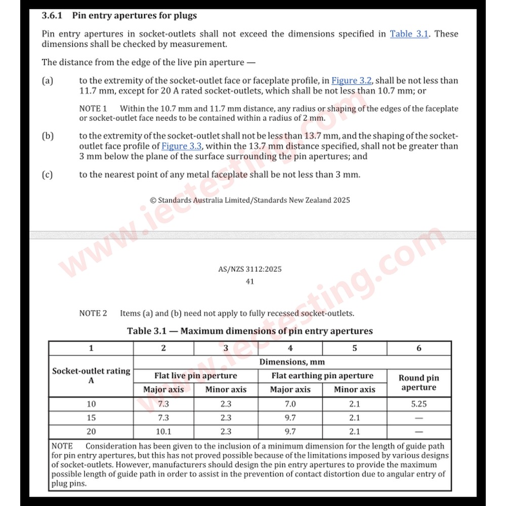
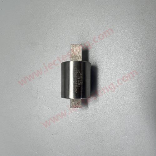
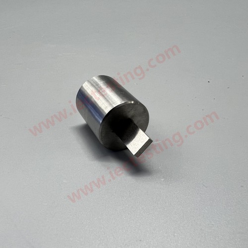
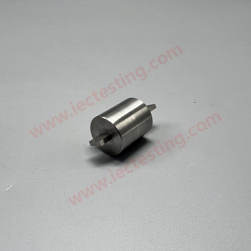
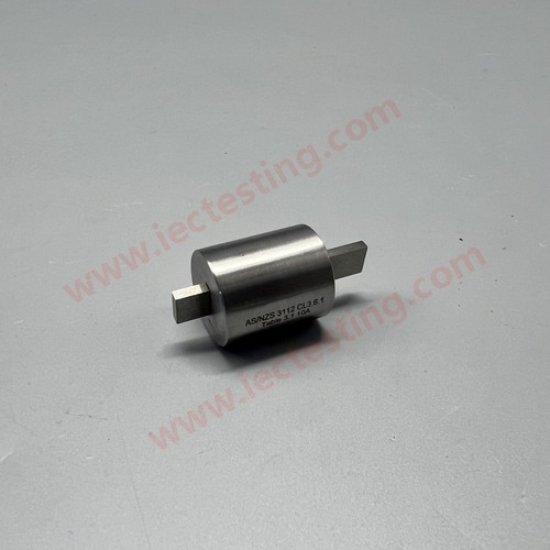
SC-AS/NZS3112-F3.1 Pin Entry Aperture Gauge Set complies strictly with AS/NZS 3112:2025 Clause 3.6.1 and Table 3.1. This set of gauges is used to verify that the pin entry apertures of socket-outlets do not exceed the maximum permitted dimensions defined in the standard. AS/NZS 3112:2025 Clause 3.6. also defines critical clearance requirements from live pin aperture edges to the socket face profile and metal faceplate: the distance from the live pin aperture extremity to the socket face profile shall meet specified minimum values, and the distance to any metal faceplate must be no less than 3 mm. Note that requirements (a) and (b) are exempt for fully recessed socket-outlets.
Table 3.1 specifies different maximum aperture dimensions for 10 A, 15 A and 20 A rated sockets, covering flat live pin apertures, flat earthing pin apertures and round pin apertures.
Specification
- Applicable Standard: AS/NZS 3112:2025 Clause 3.6.1, Table 3.1
- Gauges Included (Maximum aperture dimension probes):
- 10 A socket: Flat live pin (7.3 mm × 2.3 mm); Flat earth pin (7.0 mm × 2.1 mm)
- 15 A socket: Flat live pin (7.3 mm × 2.3 mm); Flat earth pin (9.7 mm × 2.1 mm)
- 20 A socket: Flat live pin (10.1 mm × 2.3 mm); Flat earth pin (9.7 mm × 2.1 mm)
- Round pin aperture gauge: 5.25 mm diameter (for 10 A round pin socket-outlets)
- Material: High-hardness tool steel, precision CNC machined, anti-rust surface treatment
- Test Principle: The gauge represents the maximum allowable size of pin entry aperture; if the gauge can fully enter the aperture, the socket fails the test.
- Clearance Rules from Standard:
- Minimum distance from live pin aperture extremity to face profile: 11.7 mm (10 A /15 A), 10.7 mm (20 A)
- Minimum distance from aperture extremity to metal faceplate: ≥ 3 mm
Test procedure
- Carry out dimensional measurement on each pin entry aperture of the socket-outlet and check against the maximum dimensions listed in Table 3.1.
- Verify the distance from the extremity of each live pin aperture to the socket-outlet face or faceplate profile to ensure it meets the required minimum value.
- Check the shaping of the socket-outlet face profile within the specified distance range and confirm it does not exceed the permitted recess depth.
- Measure the distance from each pin aperture to the nearest point of any metal faceplate to ensure the distance is not less than 3 mm.
- For fully recessed socket-outlets, the distance requirements in item (a) and item (b) do not need to be implemented.
- Manufacturers are recommended to design pin entry apertures with the longest practical guide path to reduce contact distortion caused by angled plug insertion.
Application
- Dimensional inspection of pin entry apertures for Australian and New Zealand socket-outlets per AS/NZS 3112:2025 Clause 3.6.1
- Pre-compliance testing before SAA certification application
- Incoming quality control and finished product inspection for socket manufacturers
- Verification of surface clearance distances between pin apertures and metal faceplates
- Test equipment for third-party electrical safety laboratories
- R&D validation during new socket-outlet mould design
Product pictures
Standard drawing