
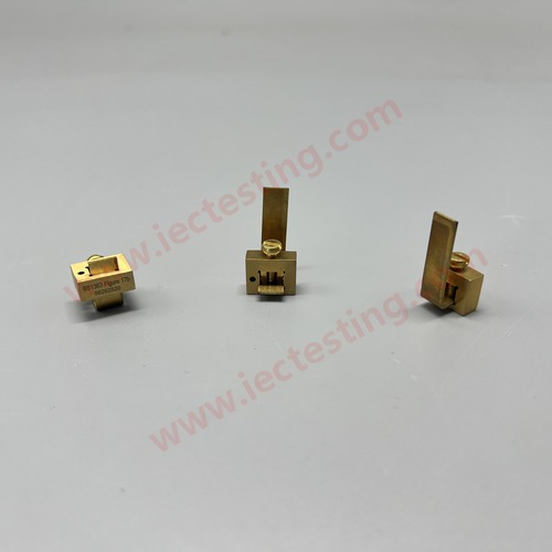
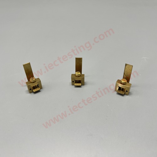
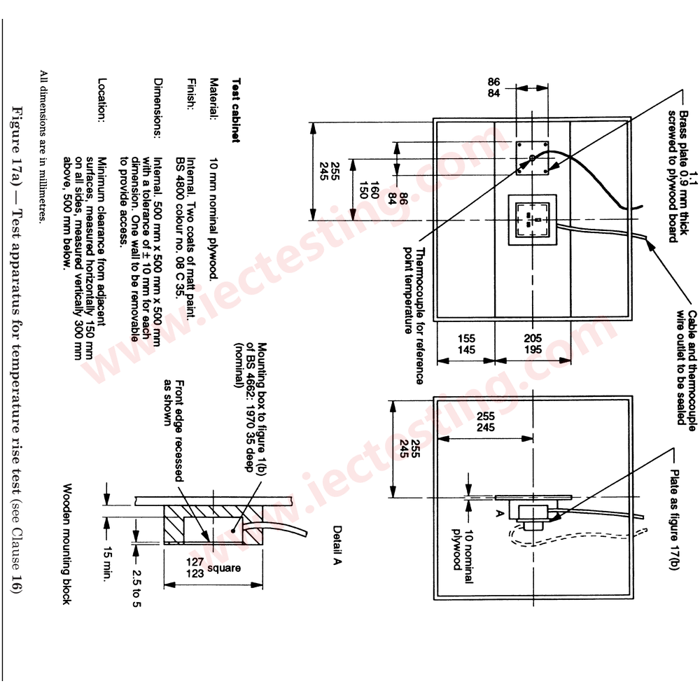
Temperature rise test arrangement to BS 1363-1 Figure 17: 17a is the test apparatus and 17b the dummy front plate with line and neutral pin spacers, so that the test conditions match the standard.
Product identification
| Item | Specification |
|---|---|
| Model | SC-BS1363-F17 |
| Figure | Figure 17a apparatus; Figure 17b dummy front plate |
| Product | BS1363 Figure 17 Temperature Rise Test Apparatus and Dummy Plate |
Product photos
Application and test method
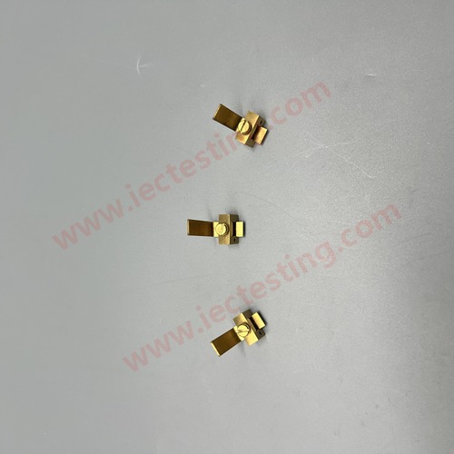
Mount the socket-outlet in the dummy plate (17b), wire per Figure 17 and pass the test current. Measure the temperature rise of each pole with thermocouples. The line and neutral pin spacers keep the pin position and the heat dissipation consistent with the standard; the length of the test conductors is also controlled.
Technical data
| Item | Specification |
|---|---|
| Standard | BS 1363-1:1995 incl. A1 to A3 |
| Figure | Figure 17a apparatus; Figure 17b dummy front plate |
| Composition | Dummy plate, L pin spacer, N pin spacer (17a enclosure optional) |
| Spacer material | Nickel-plated brass |
| Plate material | Insulating laminate |
| Test conductors | Length per standard, max. 600 mm / 850 mm |
| Temperature sensing | Type K thermocouples |
| Marking | Figure 17b + serial number |
Standard drawing
Handling and maintenance
Temperature rise results are sensitive to conductor length and thermocouple placement. Assemble strictly to Figure 17 and Clause 16.
For the complete BS 1363 range of gauges and test apparatus, contact Guangzhou Shice Instrument for selection and quotation.