
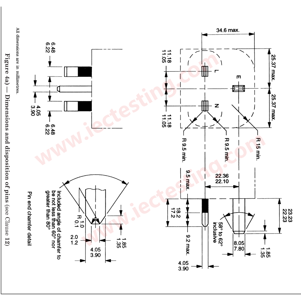
Plug-shaped gauge built to the pin dimensions and disposition of BS 1363 Figure 4, used to check the maximum withdrawal force of socket-outlet contacts. An M6 eye bolt at the rear accepts standard weights.
Product identification
| Item | Specification |
|---|---|
| Model | SC-BS1363-F4 |
| Figure | Figure 4 – Dimensions and disposition of pins |
| Product | BS1363 Figure 4 Socket-outlet Maximum Withdrawal Gauge |
Product photos
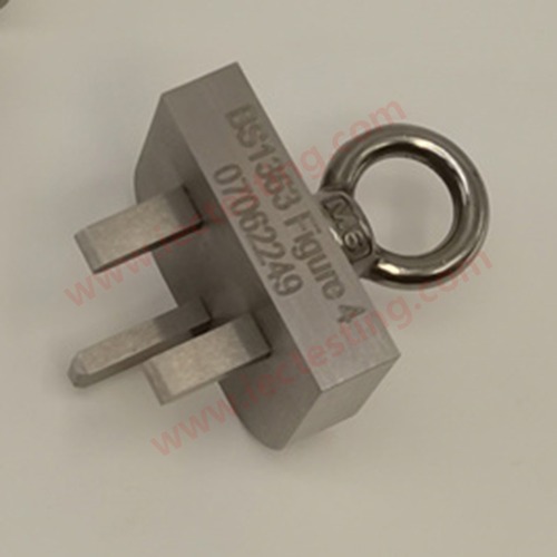
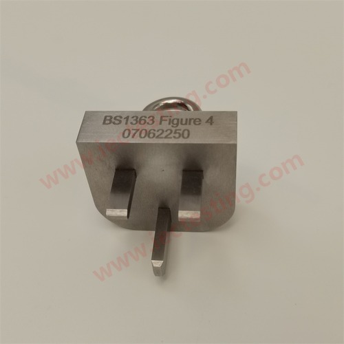
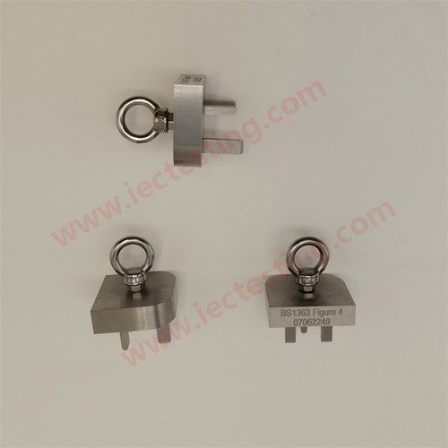
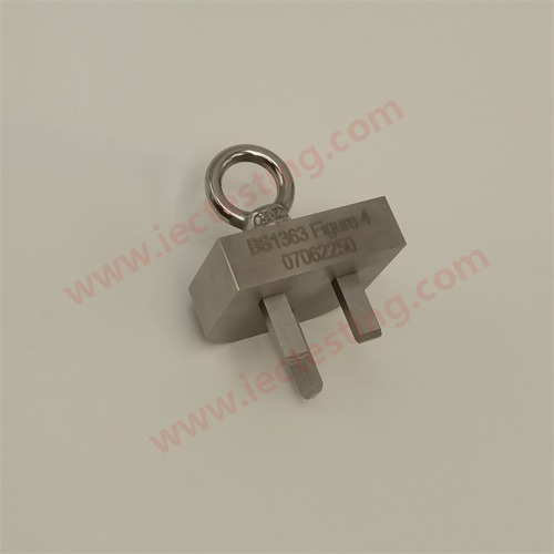
Application and test method
Insert the gauge into the socket-outlet under test until the contacts grip the pins, then add weights progressively to the eye bolt. The load at which the gauge separates from the socket-outlet is the maximum withdrawal force. The same gauge can be used as a reference plug in insertion / withdrawal endurance tests.
Technical data
| Item | Specification |
|---|---|
| Standard | BS 1363-1:1995, BS 1363-3:1995 |
| Figure | Figure 4 – Dimensions and disposition of pins |
| Pins | 3 pins (L / N / E), dimensions and centres to Figure 4 |
| Pin material | Hardened stainless steel, precision ground |
| Body | Anodised aluminium alloy or stainless steel (option) |
| Eye bolt | M6 stainless steel, accepts standard weights |
| Weight | approx. 120 g including eye bolt |
| Marking | BS1363 Figure 4 + serial number |
Standard drawing
Handling and maintenance
Make sure the socket-outlet is isolated before inserting the gauge. Re-verify pin dimensions periodically; replace the gauge once it is worn beyond tolerance.
For the complete BS 1363 range of gauges and test apparatus, contact Guangzhou Shice Instrument for selection and quotation.