
Product overview:
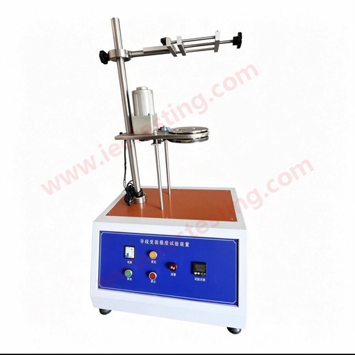
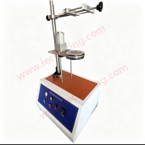
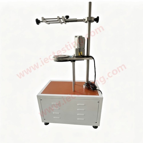
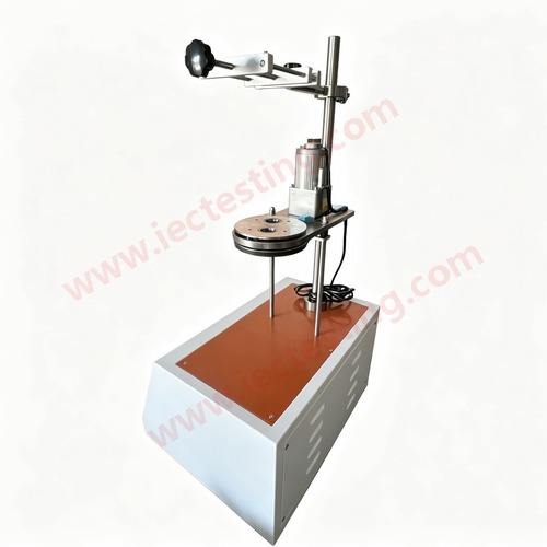
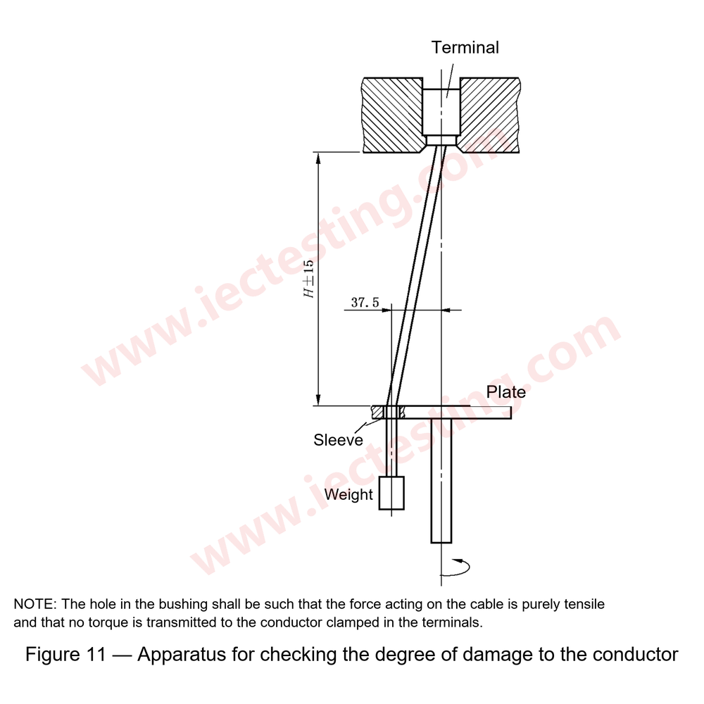
This Clamping Device Test Machine (models SC-XL03) is the test apparatus for checking the damage degree of conductors, conforming to IEC 60884-1 Figure 11 (GB 2099.1 Figure 11), VDE 0620 and IEC 60947-1 Figure 1. It is used to judge whether the design and structure of terminals with screw clamping clamp the conductor(s) without undue damage, and whether the clamping unit can withstand the mechanical stress occurring during normal use.
The testing times can be preset before the test, and the machine stops automatically with an alarm signal when the preset times are reached.
Application / Test procedure:
Terminals with screw clamping shall be so designed and constructed that they clamp the conductor(s) without undue damage to the conductor(s). Compliance is checked by the apparatus of checking damage.
- The terminal is placed in the test apparatus and fitted with rigid, solid, stranded and/or flexible conductor(s), according to the standard, first with the smallest and then with the largest nominal cross-sectional area, the clamping screw(s) or nut(s) being tightened with the torque according to the standard.
- The length of the test conductor shall be 75 mm longer than the height (H) specified in the standard.
- The end of the conductor is passed through an appropriate bushing in a plate positioned at a height (H) below the equipment. The bushing is positioned in a horizontal plane such that its centre line describes a circle of 75 mm diameter, concentric with the centre of the clamping unit in the horizontal plane; the platen is then rotated at a rate of (10 ± 2) r/min.
- The distance between the mouth of the clamping unit and the upper surface of the bushing shall be within ±15 mm of the height specified in the standard. The bushing may be lubricated to prevent binding, twisting, or rotation of the insulated conductor.
- A mass as specified in the standard is suspended from the end of the conductor. The duration of the test is approximately 15 min.
- During the test, the conductor shall neither slip out of the clamping unit nor break near the clamping unit, nor shall the conductor be damaged in such a way as to render it unfit for further use.
Technical parameters:
| Power supply | 220V AC 50Hz (115V 60Hz optional) |
| Rate of testing | (10 ± 2) r/min |
| Range of counting number | 0~9999 (150 times (15 min) by default) |
| Mass for conductor | 300g / 400g / 700g / 900g / 1400g / 2000g, one piece each |
| Diameter of gyration | 75mm (rotation radius 37.5mm) |
| Diameter of bushing hole | 6.5 / 9.5 / 13 / 14.5 mm (customizable) |
| Height (H) | 260 / 280 / 300 / 320 mm, ±15 mm |
| Dimensions | 350 × 570 × 960 mm |
| Conforms to standard | IEC 60884-1 Figure 11, GB 2099.1 Figure 11, VDE 0620, IEC 60947-1 Figure 1 |
Relation between nominal cross-sectional area of conductor, bushing hole, height and mass:
| Nominal cross-sectional area of conductor ( mm²) | Diameter of bushing Hole( mm) | Height (mm) | Mass for conductor (kg) |
| 0.5 | 6.5 | 260 | 0.3 |
| 0.75 | 6.5 | 260 | 0.4 |
| 1.0 | 6.5 | 260 | 0.4 |
| 1.5 | 6.5 | 260 | 0.4 |
| 2.5 | 9.5 | 280 | 0.7 |
| 4.0 | 9.5 | 280 | 0.9 |
| 6.0 | 9.5 | 280 | 1.4 |
| 10.0 | 9.5 | 280 | 2.0 |
| 16.0 | 13.0 | 300 | 2.9 |
| 25.0 | 13.0 | 300 | 4.5 |
| 35 | 14.5 | 320 | 6.8 |
| 1 The height tolerance: ±15mm.
2 If the bushing-hole diameter is not large enough, you can choose the larger one. |
|||
Picture view:
Standard drawing:
Related products: