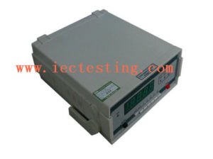
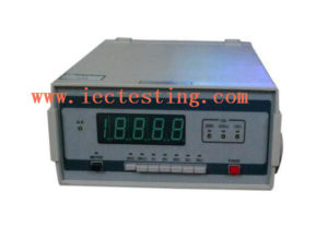
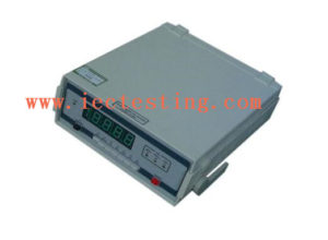
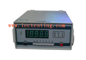
Precision IEC Test Equipment Digital DC Double Bridge For Low Resistance Resistors
- Use and features
QJ84, a new generation product replacing the Kelvin bridge device, is applicable to the precision measurement of D.C. low resistance resistors in the fields such as mines and enterprises, laboratories, workshops, etc.
Its main features are as follows:
1.1. Using a green digital display with 4½ byte LED, users can have audio-visual clear readings and rapid measurement.
1.2. The device has a wide measurement scope (0~20kΩ) which is divided into 7 ranges, with the minimum resolution being 1μΩ.
1.3. Its main resistance elements are made up of precision wire wound resistors manufactured with established technologies. Therefore, they have the properties of high degree of accuracy, small temperature coefficient and long-term stability.
1.4. Due to the integrated standard resistor, the device can calibrate the accuracy of its own accord without an external standard.
Technical parameters:
-
Specifications
2.1 Environment requirement:
Reference conditions:
Temperature: 20±2℃.
Relative humidity: 40%~60%.
Standard conditions:
Temperature: 5~35℃.
Relative humidity: 25%~75%.2.2 As for the parameters for each measurement range, please refer to Table .1.
| Rang | Effective range | Resolution | Intrinsic error | Imax |
| 20m Ω | 0~19.999m Ω | lμΩ | ± (0.5%Rx+5bd) | 1A |
| 200m Ω | 0~199.99m Ω | 10μΩ | ± (0.2%Rx+3bd) | 1A |
| 2Ω | 0~1.9999 Ω | 100μΩ | ± (0.l%Rx+2bd) | 100mA |
| 20Ω | 0~19.999 Ω | 1m Ω | ± (0.05% Rx+2bd) | 100mA |
| 200Ω | 0~199.99 Ω | 10m Ω | ± (0.05%Rx+2bd) | 10mA |
| 2kΩ | 0~1.9999k Ω | 100m Ω | ± (0.05%Rx+2bd) | 1mA |
| 20k | 0~19.999k Ω | 1Ω | ± (0.05%Rx+2bd) | 0.1mA |
2.3 Mains supply: AC 115V or 220V ±10%, 50~60Hz.
2.4 Dimensions: 250mm×110mm×285mm
2.5 Weight: 2.2kg.
- Operation principles
The operational principle for QJ84 is shown in Figure 1.The measured resistor connected to the device by the four-terminal button method, together with the reference resistor and precision operational amplifier in the range network, constitutes a half bridge circuit. After R/V conversion and A/D change, the LED digital screen will display the measurement data. The decimal point will be aligned while the changeover circuit for the range is changing the resistance of the range network.
- Structure
The structure and the layout of the QJ84 front and back cover are shown in Figure 2.
- Notes
5.1 In measuring AC resistance of some appliances which have high inductance such as transformers, cutting off the return circuit is by no means allowed, neither is the change-over of ranges after pushing the “METER” switch in the course of the measurement in order to prevent counter electromotive force. After completion of the measurement or when making any change in the range, the “METER” switch must be first released so that the high inductance can discharge through the “METER” switch. Several seconds later, the device will automatically cut off the current and the alarm lamp ALM will be turned on. When the discharge is completed (the discharge time is determined by the inductive value), then cutting off the measuring loop can be done in order to protect the safety of both the operator and the machine.
5.2 In the course of the measurement, the measuring end is permitted to be open-circuit, but not allowed to be short circuit for long. Especially when measuring the low resistance(ranges such as 20mΩ,200mΩ,2Ω), measurement should be done in a disconnected way in order to avoid long-term short circuit status because of the high measuring current.
5.3 The commercial power is strictly not allowed to put into the measuring end. Otherwise, it will damage the machine.
5.4 Environment requirements for the storage of the device: Temperature: 0-4O℃, relative humidity is less than 80%, and there are no corrosive gases and hazardous materials in the air.


