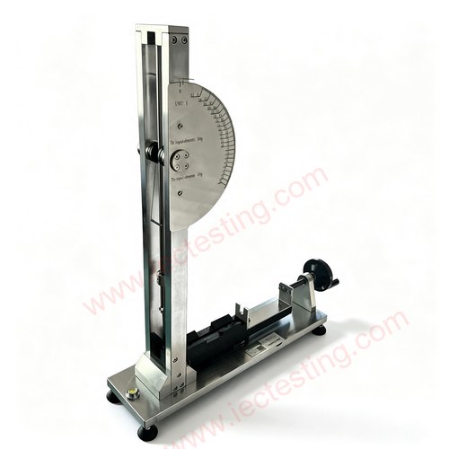
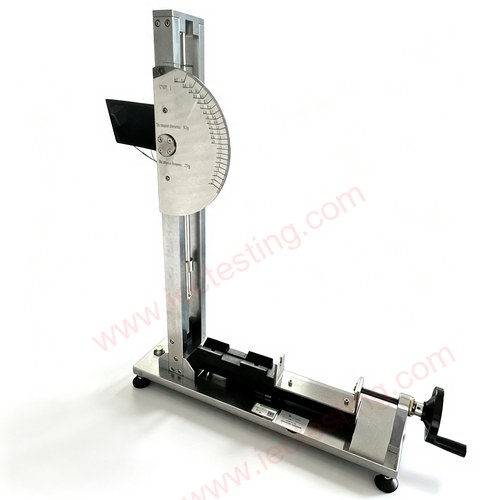
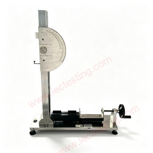
Spring Impact Hammer Calibration Device SC-CJ20 (IEC 60068-2-75) :
Product No: SC-CJ20
Standard requirement: IEC 60068-2-75 and GB2423.55. The calibration device for spring hammer is designed and manufactured according to the standard requirements of IEC 60068-2-75 Environmental testing – Part 2-75: Tests – Test Eh: Hammer tests and GB2423.55. It is used for the calibration of the spring impact hammer testers between 0 and 2 J, and is special equipment for laboratories such as third-party testing institutions, national entry-exit administration departments and electrical research institutes.
Calibration principle
Because it is difficult to measure directly the energy offered by the calibrated spring hammer, the calibration principle of this device is to compare it with the energy of a pendulum, which is calculated from the mass of the pendulum and the height of fall.
The highest resolution capability of this device is 0.01 J. The release mechanism is improved in the design so that vibration affecting the test when the spring hammer is released is reduced to a maximum extent. The pendulum rod and aerospace bearing are made of imported good quality steel to improve the precision and stability of the device.
Construction
The assembled calibration device is shown in IEC 60068-2-75 Figure B.1. Apart from the frame, the main parts are a bearing “a”, a drag pointer “b”, a pendulum “c”, a release base “d” and a release device “e”.
Key specification
| Accuracy | 0.01 J |
| Repeatability | ± 0.01 J |
| The maximum measuring range | 0 – 2 J |
| Impact energy | Max. 2 J |
| Guide groove diameter | 51 mm |
| Pendulum | Steel |
| The energy loss of the pendulum | < 0.002 J |
| Trigger distance | > 30 mm |
| Counterweight | Copper weight cover × 1 (2 J) |
| Reference | IEC 60068-2-75 Figure B.1 |
Procedure for the calibration of spring hammers
B.1 Principle of calibration: the energy provided by a spring hammer, which is difficult to measure directly, is compared with the energy of a pendulum, calculated from its mass and height of fall.
B.3 Method of calibration of the calibration device: the calibration is effected by using a calibration striking element “g” taken from a spring hammer, suspended by four linen threads from suspension points situated in a horizontal plane 2000 mm above the point of contact. The calibration is made with an impact energy of 1 J, which is achieved with a height of fall of 408 mm ± 1 mm, with a calibration striking element of 250 g. The 1 J point on the scale plate is the average of the indications of the drag pointer after at least 10 repeated operations, and the other points of the scale (0.1 J up to 0.9 J and beyond) are derived by equal division of the distance between the 0 J point and its orthogonal projection, as described in Figure B.6.
B.4 Use of the calibration device: the spring hammer to be calibrated is put in the release base and is then operated three times by means of the release device; it shall not be released manually. For each operation, the striking element of the spring hammer is turned in a different position. The average value of the three readings on the calibration device is taken to be the actual value of the impact energy of the specimen.
Notice and maintenance
- The pendulum rod shall not have any swing before the spring hammer tester is triggered.
- Stop swinging the release wheel after the spring hammer tester is triggered.
- Operating environment: 25 ± 5 ℃, relative humidity 60 – 80 %, prevent vibration.
- Lubricant shall not be added on the friction sheet of the pointer; if cleaning is needed, please use alcohol.
Standard figure
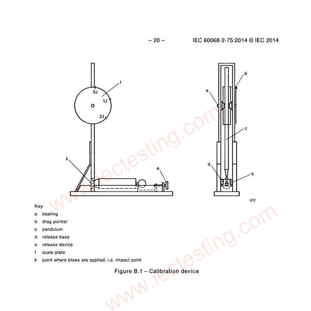
Product pictures