
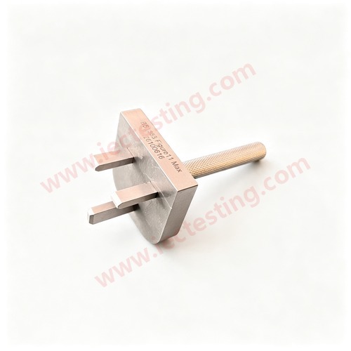
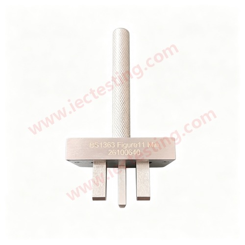
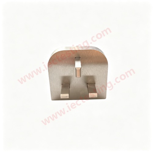
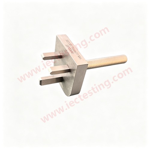
Pair of socket-outlet go gauges to BS 1363 Figure 11. The maximum and minimum pin gauges represent the two limits of plug pin size and are used to check socket entry holes, contact position and ease of insertion.
Product identification
| Item | Specification |
|---|---|
| Model | SC-BS1363-F11 |
| Figure | Figure 11 – GO gauge for socket-outlet |
| Product | BS1363 Figure 11 Socket-outlet GO Gauges (Max / Min Pin) |
Product photos
Application and test method
The maximum-pin gauge shall enter the socket entry holes and seat fully, proving the holes are not too small. With the minimum-pin gauge inserted, the contacts shall grip it and give the specified contact force, proving the holes are not too large. The two gauges together give the dimensional verdict on the socket entry.
Technical data
| Item | Specification |
|---|---|
| Standard | BS 1363-1:1995, BS 1363-2:1995 |
| Figure | Figure 11 – GO gauge for socket-outlet |
| Composition | 1 maximum-pin gauge + 1 minimum-pin gauge |
| Socket type | 13 A three-pin BS 1363 socket-outlet |
| Pin material | Hardened stainless steel, radiused edges |
| Body | Anodised aluminium alloy |
| Weight | approx. 100 g each |
| Marking | MAX / MIN + serial number |
Standard drawing
Handling and maintenance
Keep and use the two gauges as a pair; mixing gauges from different batches can bias the verdict.
For the complete BS 1363 range of gauges and test apparatus, contact Guangzhou Shice Instrument for selection and quotation.