
SC-B5F19-15A
Product overview
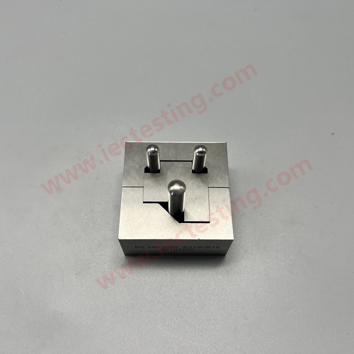
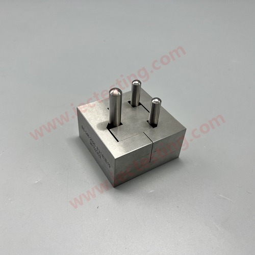
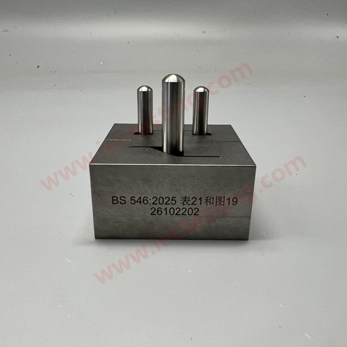
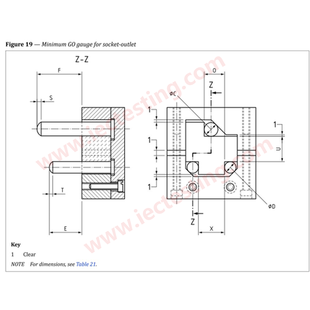
BS 546:2025 Table 21 and Figure 19 minimum GO gauge for socket-outlet, 15 A three-pin version, model SC-B5F19-15A. It is used together with the maximum GO gauge: the maximum gauge proves that a full-size plug enters, the minimum gauge proves that a plug with minimum pins still engages properly when the contact tubes are at their manufacturing limits. Only when both pass is the insertion space of the socket-outlet acceptable.
Standard: BS 546:2025 Table 21 tabulates U, X, C, D, E, F, O, S and T for the 2 A to 30 A ratings, with O = (X + C)/2, and Figure 19 gives the form of the gauge. This item is the 15 A row.
Test procedure: insert the three pins into the contact tubes; the gauge shall go fully home without jamming. Because the positioning dimensions U and X are smaller than V and Y of the maximum gauge, this gauge exposes contact tubes that are too close together, too deep, or guidance holes that are off position.
Construction
- Stainless steel body, hardened and ground, HRC 58 min.
- Pins to the 15 A row of Table 21: earth ØC 8.74 mm, current-carrying ØD 7.09 mm
- Positioning dimensions U 17.53 / X 18.16 mm, O = (X + C)/2 = 13.45 mm
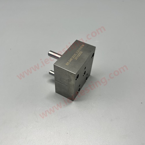
- Body stamp: BS 546:2025 表21和图19 plus serial number
- Measured dimension data and calibration certificate supplied with the goods
Technical parameters
| Model | SC-B5F19-15A |
| Standard | BS 546:2025 Table 21 and Figure 19 |
| Rating / poles | 15 A / 3-pin (2P+E) |
| U | 17.53 mm (+0.00 / -0.01) |
| X | 18.16 mm (+0.00 / -0.01) |
| C (earth pin Ø) | 8.74 mm (+0.00 / -0.01) |
| D (current-carrying pin Ø) | 7.09 mm (+0.00 / -0.01) |
| E (pin length) | 21.67 mm (+0.00 / -0.01) |
| F | 29.62 mm (+0.00 / -0.01) |
| O = (X+C)/2 | 13.45 mm (+0.00 / -0.01) |
| S | 2.36 mm (+0.25 / -0.00) |
| T | 1.98 mm (+0.25 / -0.00) |
| Material | Stainless steel, hardened and ground, HRC 58 min. |
| Body stamp | BS 546:2025 表21和图19 + serial number |
BS 546:2025 Table 21 – dimensions of the minimum GO gauge (15 A row highlighted)
| Rating A | U (mm) | X (mm) | C (mm) | D (mm) | E (mm) | F (mm) | O = (X+C)/2 (mm) | S (mm) | T (mm) |
| 2 | 8.04 | 10.74 | 5.11 | 3.58 | 13.74 | 16.92 | 7.93 | 1.57 | 1.17 |
| 5 | 13.83 | 13.79 | 7.09 | 5.11 | 16.92 | 21.67 | 10.44 | 1.98 | 1.57 |
| 15 | 17.53 | 18.16 | 8.74 | 7.09 | 21.67 | 29.62 | 13.45 | 2.36 | 1.98 |
| 30 | 26.34 | 28.40 | 9.55 | 7.95 | 29.62 | 37.54 | 18.97 | 2.77 | 2.36 |
| Tolerance | +0.00/-0.01 | +0.00/-0.01 | +0.00/-0.01 | +0.00/-0.01 | +0.00/-0.01 | +0.00/-0.01 | +0.00/-0.01 | +0.25/-0.00 | +0.25/-0.00 |
NOTE The radiated ends of the plug pin portions of the gauge shall be part of a sphere.
Product pictures
Standard drawing
Related products
- BS 546:2025 Table 20 / Figure 18 Maximum GO Gauge for Socket-outlet 15A SC-B5F18-15A
- BS 546:2025 Figure 22 Gauge for Verifying Resistance to Lateral Stress 15A SC-B5F22-15A
- BS 546:2025 Table 18 Gauges for Non-interference of Switch and Plug 15A SC-B5T18-15A
- SANS 164-1 Annex A Gauge for Distance to Current-carrying Contact Tubes 15A SC-S164A-15A
- SANS 164-1 Annex B No-contact Gauge 15A SC-S164B-15A
- SANS 164-1 Annex C Contact Gauge 15A SC-S164C-15A
- SANS 164-1 Annex D Gauges D1 and D2 for Single-pole Insertion 15A SC-S164D-15A
- BS546 Figure 21 Withdrawal-pull Gauge 15A Current-carrying / Earthing
- BS546 Clause 10.6.2 5N Rigid Metal Pin Test Pin
- BS546 British Standard Plugs Socket Outlets Gauges – full range